Table of Contents
Quadratic Bezier and Cubic Bezier without LERP
There are lots of functions out there that use LERP (Linear Interpolation) functions, but we may want to achieve the same thing but without using LERP. The two functions below do this, and are derived from the Bezier math constructs. Now we have this, it can easily be interpolated two another language such as EKL and used within Actions, Rules and Knowledge Patterns. I will also be looking at the derivatives to calculate curvature, and acceleration at a given point.
Equations
The following equations define the Bezier equations for 2,3, and 4 point Bezier curves, where t is a value between 0 and 1.
- P = (1-t)P1 + tP2 // Straight Line 2pts
- P = (1−t)2P1 + 2(1−t)tP2 + t2P3 // Quadratic Curve 3pts
- P = (1−t)3P1 + 3(1−t)2tP2 +3(1−t)t2P3 + t3P4 // Cubic Curve 4pts
Note these formulas can be expanded for X, Y and Z values i.e.
P.X = (1-t) * P1.X + t*P2.X \\
P.Y =  (1-t) * P1.Y + t*P2.Y \\
P.Z =  (1-t) * P1.Z + t*P2.Z \\
C# Code
		Point quadraticBezier(Point p0, Point p1, Point p2, double t, Point? returnPoint = null)
		{
			returnPoint = returnPoint ?? new Point();

			returnPoint.X = Pow((1 - t), 2) * p0.X +
								2 * (1 - t) * t * p1.X +
								Pow(t, 2) * p2.X;

			returnPoint.Y = Pow((1 - t), 2) * p0.Y +
								2 * (1 - t) * t * p1.Y +
								Pow(t, 2) * p2.Y;

			returnPoint.Z = Pow((1 - t), 2) * p0.Z +
								2 * (1 - t) * t * p1.Z +
								Pow(t, 2) * p2.Z;

			return returnPoint;
		}

		Point cubicBezier(Point p0, Point p1, Point p2, Point p3 ,double t, Point? returnPoint = null)
		{
			returnPoint = returnPoint ?? new Point();

			returnPoint.X = Pow((1 - t) ,3) * p0.X +
								3 * Pow((1 - t), 2) * t * p1.X +
								3 * (1 - t) * Pow(t, 2) * p2.X +
								Pow(t, 3) * p3.X;

			returnPoint.Y = Pow((1 - t), 3) * p0.Y +
								3 * Pow((1 - t), 2) * t * p1.Y +
								3 * (1 - t) * Pow(t, 2) * p2.Y +
								Pow(t, 3) * p3.Y;

			returnPoint.Z = Pow((1 - t), 3) * p0.Z +
								3 * Pow((1 - t), 2) * t * p1.Z +
								3 * (1 - t) * Pow(t, 2) * p2.Z +
								Pow(t, 3) * p3.Z;

			return returnPoint;
		}

		Point linearBezier(Point p0, Point p1, double t, Point? returnPoint = null)
        {
			returnPoint = returnPoint ?? new Point();

			returnPoint.X = (1 - t) * p0.X + t * p1.X;
			returnPoint.Y = (1 - t) * p0.Y + t * p1.Y;
			returnPoint.Z = (1 - t) * p0.Z + t * p1.Z;

			return returnPoint;
		}

		private double Pow(double x, double y)
        {
			return System.Math.Pow(x, y);
		}
Cubic Bezier Curve Construction
A Cubic Bezier curve is constructed from four points, and based on the Quadratic equation a curve can be created. This can also be created via geometry.
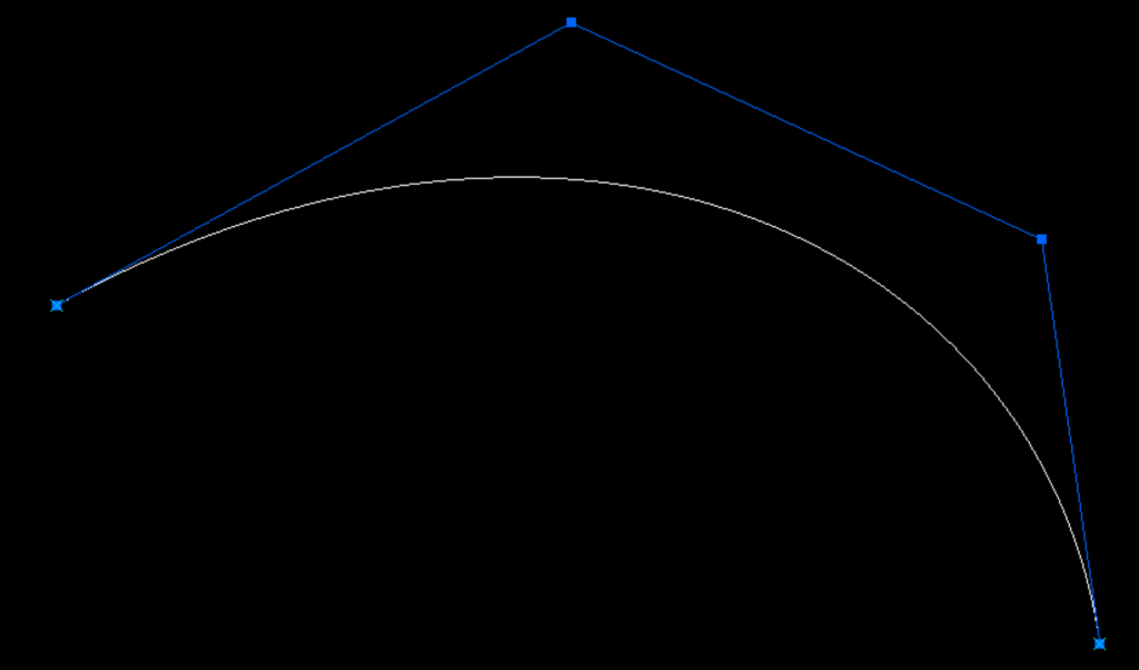
If we connect the four point from left to right with three lines (purple) and then create three points on those lines at a ratio position in this case 0.25. Then connect those points with two lines (Yellow) and create two points on those lines at a ratio position of 0.25. Then connect those point with a line (green) that has a point at a ratio of 0.25. We will find that the point (Red) is on the Cubic Bezier Curve.
If we change the ratio points value for all points we will see the Red point travel along the Cubic Bezier Curve.
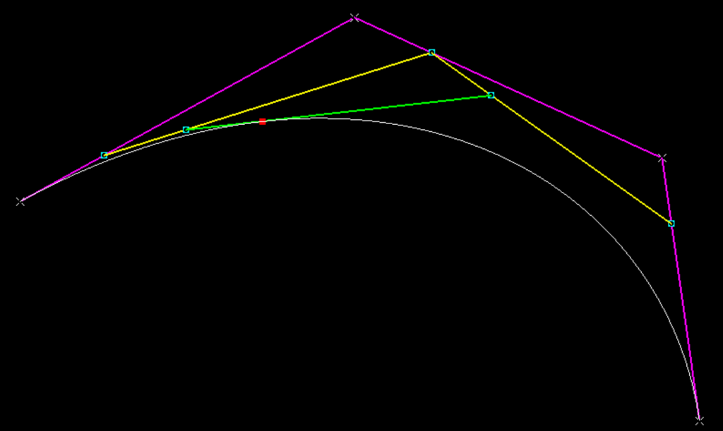
Cubic Bezier Construction within a Knowledge Pattern using EKL
So we can now write a Knowledge Pattern to create points along the Cubic Bezier Curve.
Let iPoint0 , iPoint1 , iPoint2 , iPoint3 ( Point )
iPoint0 = `Geometrical Set.1\Point.1`
iPoint1 = `Geometrical Set.1\Point.2`
iPoint2 = `Geometrical Set.1\Point.3`
iPoint3 = `Geometrical Set.1\Point.4`

Let iNumber , iIndex( Integer )
iNumber = 100
iIndex = 1

For iIndex While iIndex < iNumber
{
	Let t ( Real )
	t = (1/iNumber) * iIndex

	Let X , Y , Z ( Length )
	X =(1-t)**3 * iPoint0->coord(1) + 3*(1-t)**2*t*iPoint1->coord(1) +3*(1-t)*t**2*iPoint2->coord(1) +t**3*iPoint3->coord(1)
	Y =(1-t)**3 * iPoint0->coord(2) + 3*(1-t)**2*t*iPoint1->coord(2) +3*(1-t)*t**2*iPoint2->coord(2) +t**3*iPoint3->coord(2)
	Z =(1-t)**3 * iPoint0->coord(3) + 3*(1-t)**2*t*iPoint1->coord(3) +3*(1-t)*t**2*iPoint2->coord(3) +t**3*iPoint3->coord(3)

    Let ioKPPoint ( Point )
	ioKPPoint = CreateOrModifyDatum( "Point" , `Geometrical Set.2` , `Relations\Knowledge Pattern.1\Points` , NULL )
	ioKPPoint  = point( X,Y,Z)
	ioKPPoint->SetAttributeReal("Ratio",t)
}
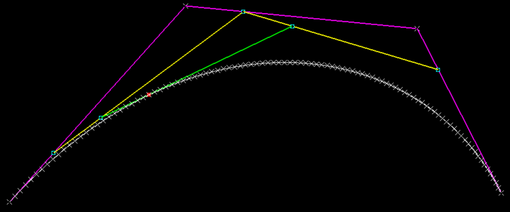
When the Knowledge Pattern is executed we can see that the generated points are perfectly on top of the Cubic Bezier Curve.
Quadratic Bezier Curve Construction
A Quadratic Bezier curve is constructed from three points, and based on the Quadratic equation a curve can be created. This can also be created via geometry.
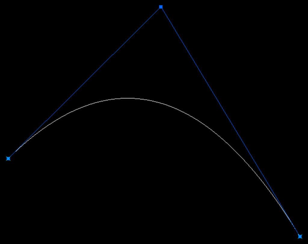
Using the same construction technique we used in the Cubic Bezier Curve, we can define based on a ratio value the point locations along Quadratic Bezier curve.

Quadratic Bezier Construction within a Knowledge Pattern using EKL
Again we can now write a Knowledge Pattern to create points along the Quadratic Bezier Curve.
Let iPoint0 , iPoint1 , iPoint2 ( Point )
iPoint0 = `Geometrical Set.1\Point.1`
iPoint1 = `Geometrical Set.1\Point.2`
iPoint2 = `Geometrical Set.1\Point.3`

Let iNumber , iIndex( Integer )
iNumber = 100
iIndex = 1

For iIndex While iIndex < iNumber
{
	Let t ( Real )
	t = (1/iNumber) * iIndex

	Let X , Y , Z ( Length )
	X=(1−t)**2 * iPoint0->coord(1) + 2 * t * (1−t) * iPoint1->coord(1) + t**2 * iPoint2->coord(1)
	Y=(1−t)**2 * iPoint0->coord(2) + 2 * t * (1−t) * iPoint1->coord(2) + t**2 * iPoint2->coord(2)
	Z=(1−t)**2 * iPoint0->coord(3) + 2 * t * (1−t) * iPoint1->coord(3) + t**2 * iPoint2->coord(3)

    Let ioKPPoint ( Point )
	ioKPPoint = CreateOrModifyDatum( "Point" ,`Geometrical Set.4`  , `Relations\Knowledge Pattern.2\Points` , NULL )
	ioKPPoint  = point( X,Y,Z)
	ioKPPoint->SetAttributeReal("Ratio",t)
}
When the Knowledge Pattern is executed we can see that the generated points are perfectly on top of the Quadratic Bezier Curve.
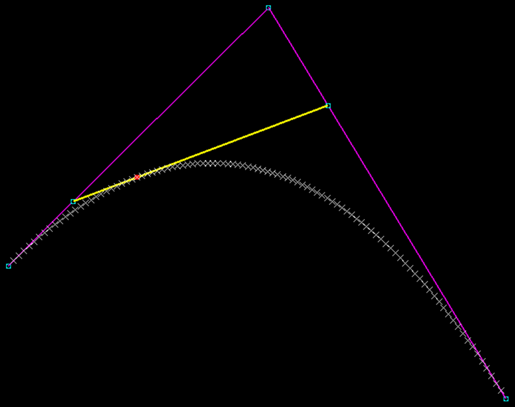
Linear Bezier Curve Construction
Finally, if we simplify the equation yet again we can interpolate between two points.

Linear Bezier Construction within a Knowledge Pattern using EKL
Let iPoint0 iPoint1 ( Point )
iPoint0 = `Geometrical Set.5\Point.2297`
iPoint1 = `Geometrical Set.5\Point.2298`

Let iNumber , iIndex ( Integer )
iNumber = 100
iIndex = 1

For iIndex While iIndex < iNumber
{
	Let t ( Real )
	t = (1/iNumber) * iIndex

    Let X , Y , Z ( Length )
	X= (1-t) * iPoint0->coord(1) + t* iPoint1->coord(1)
	Y= (1-t) * iPoint0->coord(2) + t* iPoint1->coord(2)
	Z= (1-t) * iPoint0->coord(3) + t* iPoint1->coord(3)

    Let ioKPPoint ( Point )
	ioKPPoint = CreateOrModifyDatum( "Point" ,`Geometrical Set.6`  , `Relations\Knowledge Pattern.3\Points` , NULL )
	ioKPPoint  = point( X,Y,Z)
	ioKPPoint->SetAttributeReal("Ratio",t)
}
Converting the Points to a Spline in EKL
Final note we can convert our points into a spline by using the EKL Spline method
spline( `Geometrical Set.2`->Query("Point","") )
//or
spline( PointsList )
Now we have something to work with, either as an input to a sweep, or as construction for a complex surface.
